


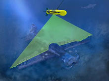
An artist's rendition of a laser line scan (LLS) system in operation. Click image for larger view and image credit.
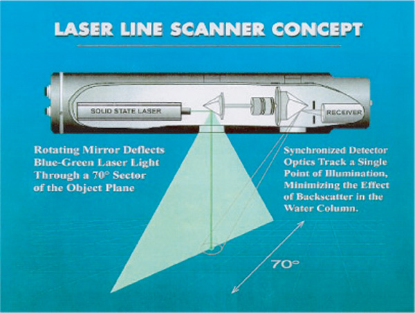
The LLS concept. Click image for larger view and image credit.
Laser Line Technology
John Rooney
Chief Scientist — Operation Laser Line 2006
Joint Institute for Marine and Atmospheric Research
Water Clarity |
Example Area |
Typical Height Above Sea Floor |
Maximum Swath Width |
Resolution (pixel size) |
Very clear |
Hawaii |
30 m |
43 m |
4.2 cm |
Clear |
San Diego |
15 m |
22 m |
2.1 cm |
Moderate |
Wash. State and Mass. Bay |
5 m |
7 m |
0.7 cm |
Poor |
Any working harbor |
2 m |
3 m |
0.3 cm |
Maui shelf are very clear and will allow the sensor to be operated at an altitude that maximizes the swath width of the survey while still maintaining an adequately high resolution. Typically, we expect to tow the LLS at a speed of 4 knots and between 5 and 30 m above the seabed, depending on the terrain and the type of seabed features. At these tow heights, the LLS provides a resolution midway between that provided by video and still imagery, but at a much higher coverage rate. In rough terrain, however, we can tow at a higher altitude and still image the seabed, although at the cost of image resolution.
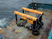
The LLS instrument is mounted on the Focus 1500, a remotely operated tow vehicle. Click image for larger view and image credit.
The LLS system has been integrated with a Focus 1500 vehicle, a remotely operated towed vehicle (ROTV) rated to operate in depths of up to 1,500 m. The vehicle provides a stable platform that can be maneuvered along survey tracklines and provides a coordinated uplink of sensor and instrumentation data over a fiber optic tow cable. It is of an open frame design that resembles a box kite. It uses four movable control surfaces, two vertical and two horizontal, to control across-track position and altitude. The ROTV is towed behind a vessel to provide the vehicle’s forward movement at speeds up to 5 knots. The Focus tow body system is used extensively around the world for offshore oil and gas applications, such as pipeline inspection. It has the desirable characteristic of being maneuverable in elevation and crosstrack position. For shallow tow applications (such as the planned survey), where bottom obstacles and other features are present, this vehicle provides an ideal platform for towing with respect to the bottom habitat.
For this survey, the ROTV will be configured to carry the SM-2000 LLS system, a TSS motion sensor (providing precise heading and vessel attitude), a Mesotech altimeter, and an IXSEA GAPS or Trackpoint II transponder. The ROTV also carries a KVH fluxgate compass and a two-axis Lucas AccuStar pitch-and-roll sensor as backup heading and attitude sensors. The transponders are part of an acoustic tracking system that is utilized to determine the position of the ROTV.
The optical data are recorded along with necessary navigation, ROTV orientation, and laser operational parameters, and are georeferenced and displayed in plain view in real time during the survey. High-resolution multibeam data will be concurrently collected during the survey operation to supplement existing bathymetry. After the survey is complete, the real-time mosaics will be georegistered with available bathymetry and imagery data. Finally, these merged data products will be used to develop benthic (sea bottom) habitat maps of the survey area.