


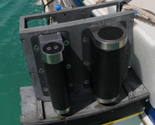
Figure 1. A Multibeam sonar transducer. Click image for larger view and image credit.
How Multibeam Sonar Works
Multibeam sonar sensors — sometimes called multibeam acoustic sensors or echo-sounders — are a type of sound transmitting and receiving system. These systems work by transmitting a sound pulse, called a ping, through a transmitter at a specific frequency, and then receiving that same pulse through a receiver placed very close to the transmitter. The transmitter and receiver are called transducers because they convert energy into another form (Figure 1). The transmitter converts an electrical signal into an acoustical pulse and the receiver converts an acoustical pulse into an electrical signal. A computer determines how long it takes to receive the returning pulse which, when the transducers are pointed toward the seafloor, translates to depth. The more time it takes for the pulse to return, the farther away the object is. Assigning a color range or grey scale for depth can create a top-side view of the seafloor.
Fast, Accurate Surveys
Multibeam sonar has several transducers that allow a large swath of area to be surveyed at once making surveying much faster and more accurate (figure 3). The swath width is determined by the depth of the seafloor being surveyed. The ping is emitted in a fan shape outward from the transmitter. The farther away the object the more area there is for the sound to echo off. The sonar pings several times per second which, with the speed of the boat, determines the horizontal resolution of the images created.
If the boat is moving very fast and the rate that the sonar unit is pinging is slow, then the number of times sound is bounced off the seafloor in the area covered is fewer than if the boat was moving slowly while the unit was set to a high ping rate. Also, if the area being covered is very deep, then the boat must move slower over that area, or the unit must use a higher ping rate, in order to achieve an equal quality image as to images at shallow depths because it takes longer for the sound pulse to return to the transducer.
The ping rate is also limited by the speed of sound in water, because with most multibeam systems the transducer must wait to receive the last ping sent before generating the next one (i.e., there can only be one ping in the water at a time). This operational constraint sets an upper limit on the ping rate for a given water depth and swath width combination. For this reason, during the Bermuda cave mapping project, when we needed the highest possible resolution achievable for these greater water depths, we narrowed down the swath angle squeezing all 500 beams into a narrower swath.
Doing so not only focused more beams on the bottom per unit area across the swath, but also reduce the maximum slant range the ping had to travel at the outer edges of the beam swath, thereby reducing the maximum ping travel time and enabling us to increase the ping rate over what we would have used at a wider swath angle (i.e., higher resolution but narrow coverage). This approach produced the very dense point cloud data set that revealed the King George wreck in such high detail (figure 6).
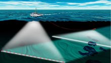
Figure 3. Use of multibeam sonar to map the seafloor. Click image for larger view and image credit.
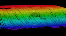
Figure 4. A multibeam image of a submarine landslide off the coast of Bermuda. In the color coded image, warm colors (red, orange, yellow) correspond to shallower water depths, while cooler colors (green, blue, purple) indicate deeper depths. Click image for larger view and image credit.
Choosing Frequencies
The frequency of the sound wave is chosen based on how far the wave has to travel. Lower frequency waves can travel farther in a medium, such as water, because the motion of these waves is closer to a straight line. They travel through the water at a more perpendicular angle, allowing them to penetrate the medium better and not attenuate, or lose intensity, as quickly as those at higher frequencies.
Higher frequency waves, because they approach the surface of the object at more of an angle, are more likely to bounce off of the object instead of passing through it, allowing for better resolution images. More returned sound waves mean better pictures. Therefore, for high resolution pictures, a high frequency sound wave is desirable; but if the seafloor is so deep that the high frequencies cannot reach, then lower frequency waves may be the better choice. If the wave attenuates before it reaches an object, no echo is returned to create an image.
Due to multibeam’s high degree of precision and accuracy achieved by time stamping each transmitted ping and precisely measuring the time and angle of its return, it is possible to create stunning three-dimensional (3D) surface models of the seafloor. These images are of such high resolution that topographic formations of the bottom (figures 4, 5) or even manmade objects, such as shipwrecks (figure 6) appear as sharp, 3D images. In order to obtain this level of accuracy, an inertial motion unit (IMU) keeps track of the sonar transducers' position several times a second. using global positioning satellites (GPS) and measuring the pitch, roll, and heading of the boat to within 0.03 200 times per second (200 hz).

Figure 5. A multibeam bathymetric map of a section of the submerged cliff line surrounding Bermuda at 100 meter (328 foot) depths. Note the vertical gullies that are cut into the cliff face. Click image for larger view and credits.

Figure 6. Multibeam image of the dredger King George that sunk in 1930 near North Rock, Bermuda. The ship sits upright on a sand bottom in 18 m (60 ft) of water. Click image for larger view and credits.
Correcting for Refraction
Bending of the ping’s path through the water due to refraction is another source of error that must be corrected for. The speed of sound in water varies with the water’s density, which is dependent upon salinity and temperature. Waters of different densities tend not to mix and they form discrete layers resulting in what is known as a stratified water column. This phenomenon is responsible for the thermocline swimmers experience when they dive below the surface and find a layer of cooler (denser) water. This layering causes the speed of each ping to change and its path to bend a little bit every time its passes through a density change.
Without correction, these speed changes and bends would result in the multibeam system inaccurately calculating where the ping hit the seafloor and the distance it traveled. To correct for refraction error, hydrographers (scientists who study, describe, and map water) must stop and do sound velocity profile (SVP) casts every couple of hours during a survey. They do this by lowering a sound velocity profiler to the bottom and back logging the depth and sound velocity.
Precision Pays Off
All of these measurements allow the computer to correct the location of objects on the seafloor relative to the sonar transducers. The more precise these measurements are, the higher the image resolution and the more detailed the seafloor maps that we can obtain from them.
Sign up for the Ocean Explorer E-mail Update List.